Fixing (and modifying)
a
Trio TS700 series PSU.
The TS700 psu is rather unusual. In addition to the usual bridge rectifier there is a voltage doubler (regulated to 20V) and a stabilised 9V rail. The voltage doubler is transformerless and works by charge pumping from a square wave (about 500Hz) from the 13.8V rail. This circuit also produces a low current -6V source. The 9V rail powers all the signal processing circuitry. The drain is 100mA on receive and 300mA on transmit. The nominal 13.8V available from the AC supply is about 17.5V. It feeds the audio amplifier and the RF amplifier if the doubler fails. The regulated 9V supply is fed from it (via D7) as well.
The 20V regulator pass transistor is located on the rear of the chassis. The nominal 20V rail should be set to 21V, according to the service manual. The setting for the 9V rail and the 20V rail interact. Both should be checked after adjustment.
Everything depends on the 9V regulator IC, Q11. If this fails only the 13.8V stays on. It is a well known issue.
Dial lights are (originally) powered from an independent regulator also on the rear of the chassis. (Because of the difficulty of obtaining pea bulbs of the correct voltage this system is often modified.)
I think there were power rail problems right from the start. The circuit board show signs of modification during production and the circuit diagrams and board layouts do not match the the reality of the actual TS700s. There are also errors in the circuit diagrams, the result of careless redrawing to accomodate changes. A critical diode, D7, is not fitted to the designated space on the pcb, but between the 13.8V and 20V rail connections of the psu can. (More about this later.)
With no direct replacement available I decided to use a modern, three terminal, variable regulator. I wanted to retain as much of the original circuit design as I could. I came to the conclusion that this was much more trouble than it was worth.
I decided to use an LM317L. I did not work. I think it would have if I had taken the original NPN pass transistor out of the voltage control loop. (A PNP transistor might have worked using the tracks on the pcb.) A fixed jacked up voltage regulator like a 78xx would work with the NPN pass transistor but I wanted to keep the component count low and the modification tidy. The more I investigated the more I learned and I came to the conclusion that I was barking up the wrong tree.
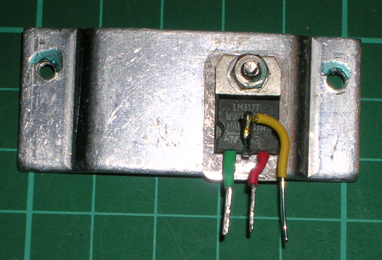
When I hooked up a separate 9V supply and found that the current levels were well within the capability of an LM317T I gave up all my ideas of reworking the original circuit. Transistors Q9 and Q10, provide protection to the original regulator and were removed. The LM317 has comprehensive protection built in. I removed Q9 and linked the emitter and collector connections. I removed Q10. I fitted an LM317T in place of the original pass transistor, Q12 and removed R26. (I had to cross the LM317 collector and emitter leads.) I kept the original voltage control pot but changed the resistors either side of it to match the LM317 requirements. The feed to the regulator was made by changing a wire link.
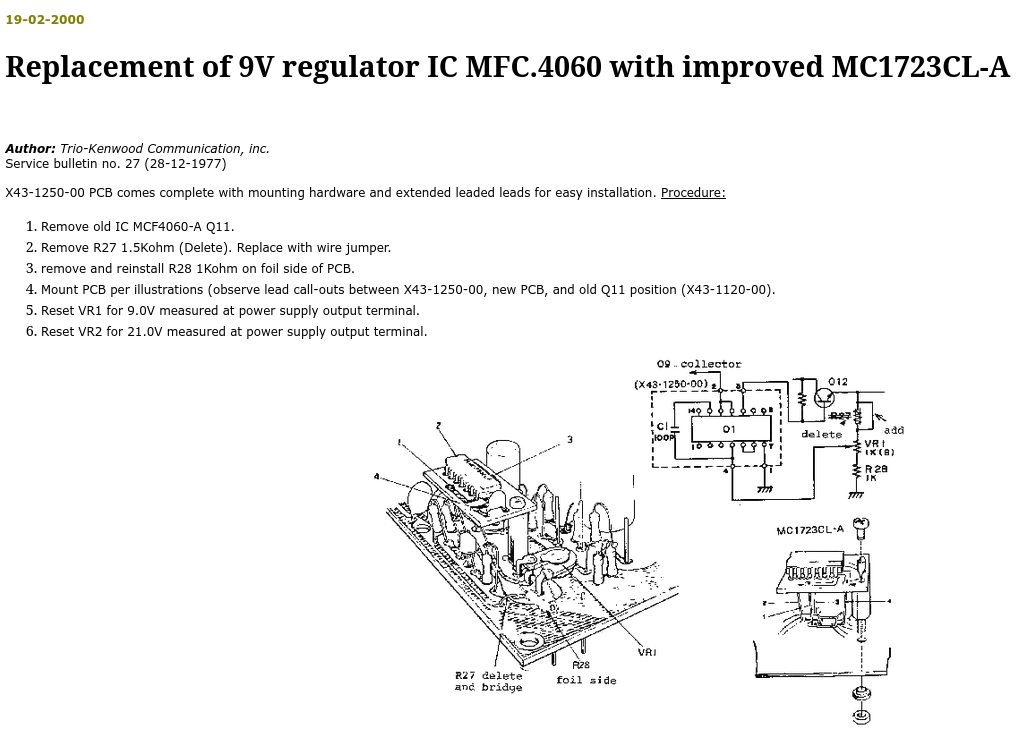
The regulator was such a problem that Trio produced a conversion board to simplify its replacement using an LM723, the regulator used in late models of the TS700. This could be reproduced using perf board. You can see the details here.
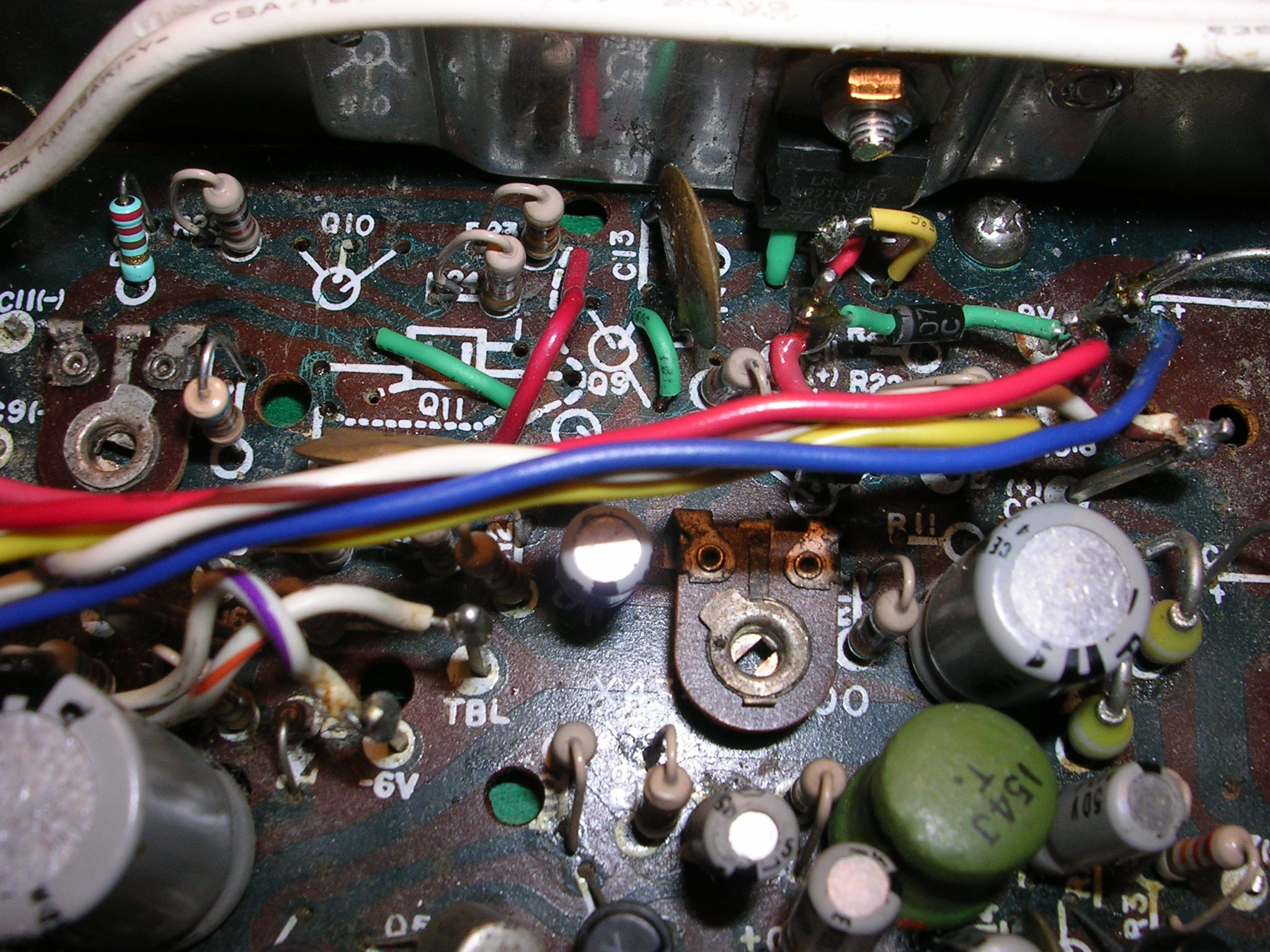
PCB Component Side - After Modification.
All these images can be opened at high resolution.
PCB Foil Side - After Modification.
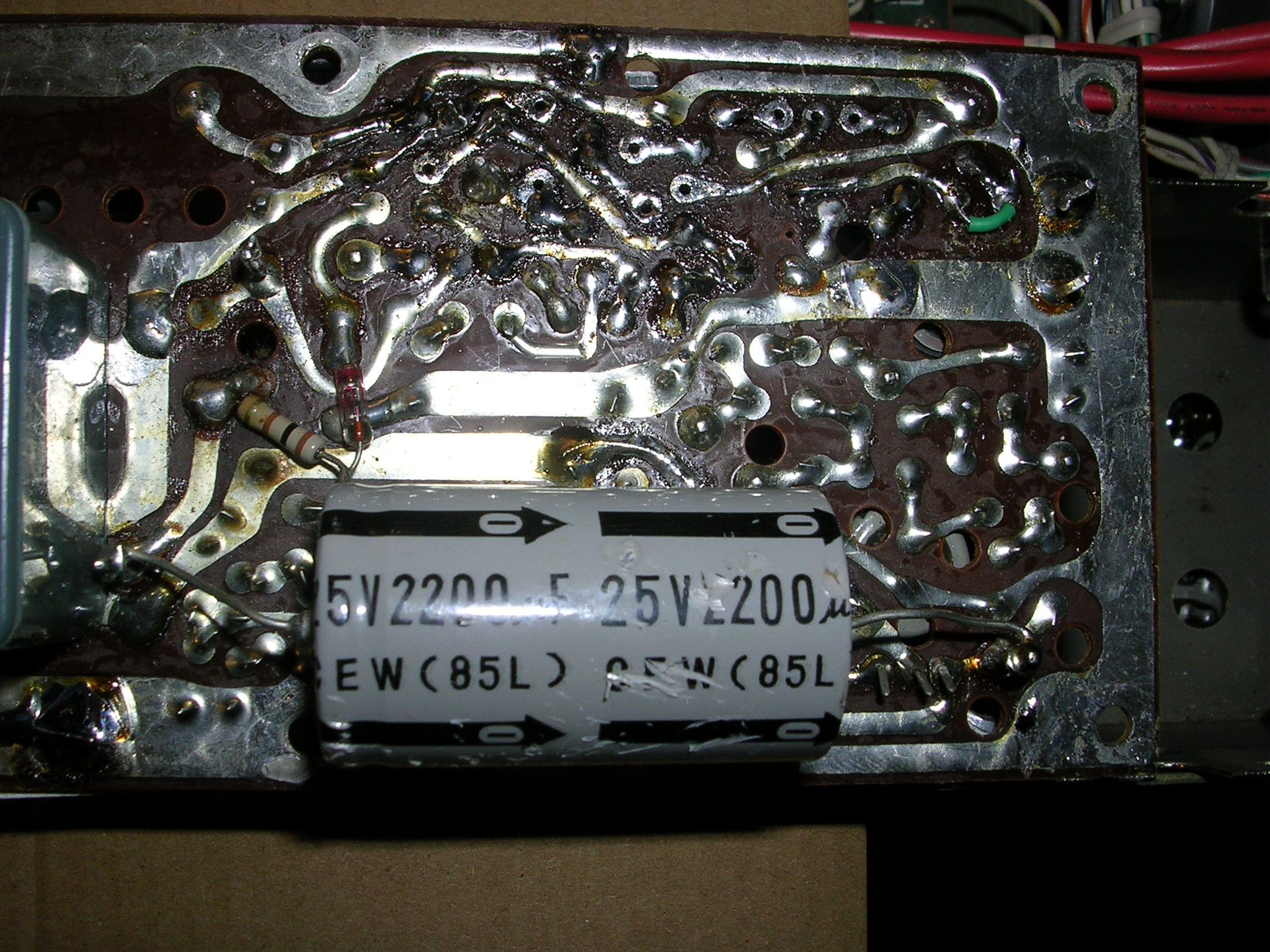
Two large capacitors have been temporarily removed
in order to gain access to the tracks.
The one that is still in place has been moved.
It will prevent the board from being replaced
unless it is dressed well away from the mounting hole.
(The radio will function without them.)
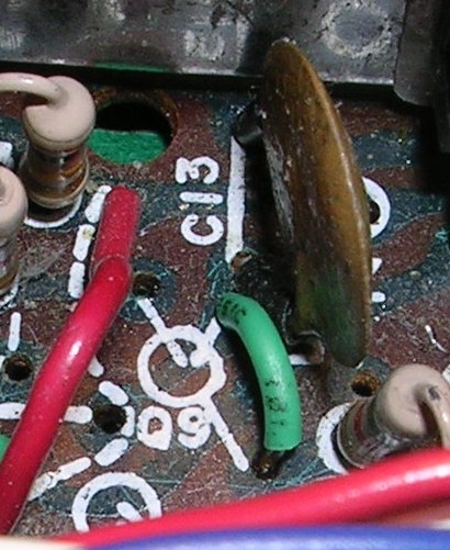
Q9, Removed, not required. Link emitter and collector. (Above pcb board.) This is more tidying up than anything else. The link retains the connection of the adjacent ceramic filter capacitor, not essential but useful.
Q10, Removed, three holes in line (horizontal), no longer required. Tidying up, (optional).
D7, is not fitted here, two holes (vertical). You will probably find it between the 20V and 13.8V feed through connections (inside the PSU).
R27 1.5K, Replaced with 220R. (Easily available value. Spec calls for 240R.)
R28 1K, Replaced with 680R. (Selected on test.)
Q12 Replaced by the LM317T, near the fixing hole.
R26, Removed. (Not replaced.) Essential.
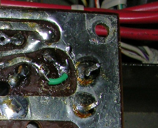
VR1
Add a wire link (green sleeved above).
The wiper of the 9V adjustment control is now linked to one end and R27 making it a variable resistor. A potentiometer is not needed. This is a safety measure that guards against over voltage resulting from a dirty contact.
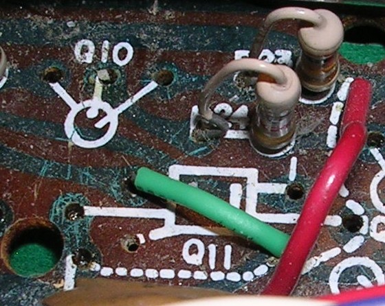
Q11, Removed (faulty regulator).
Bare Wire link, next to Q11, Removed. (the dashed line), component side of PCB.
Add a wire link (green, above) diagonally across Q11 position from near Q10 to the hole vacated by the removed wire link. This connects the voltage control wiper to the adjust terminal of the LM317T.
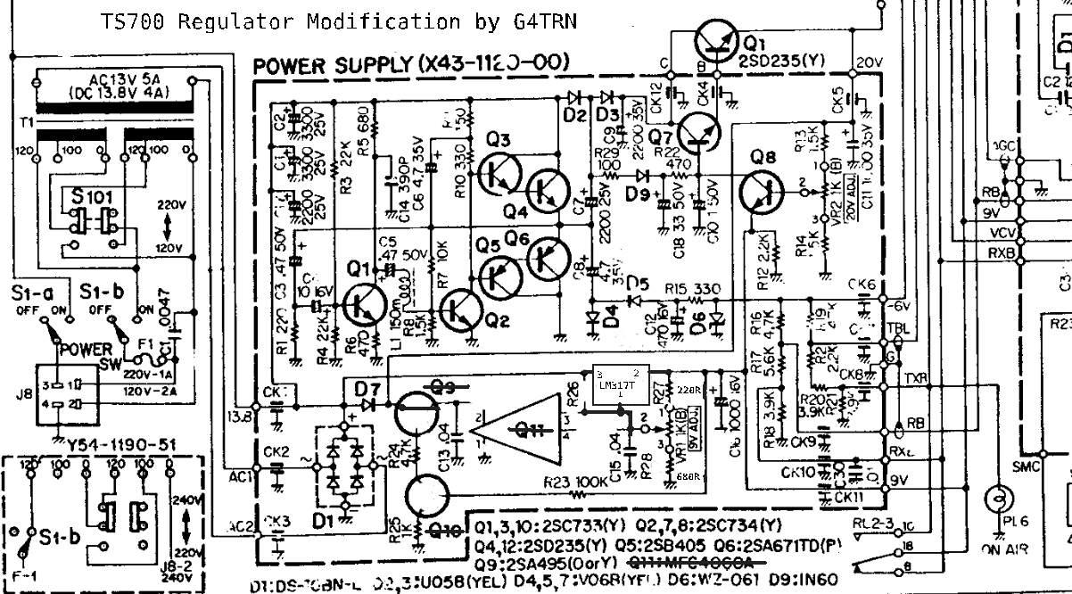
Modified schematic from a TS700G sevice manual.
Right Click it to enlarge it.
Observations
- Note the board marking for transistors. Left to right in the image above.
The EMITTER is the electrode connected to the RING.
The COLLECTOR is the DOT.
The BASE is left as a LINE. (Perhaps remember 'baseline'.) - D7 is not on the board.
It is usually connected across the first two feedthrough connectors to the PSU. You are quite likely to break it if you try to remove it while testing. A standard 1A rectifier (1N4007) will do. I have fitted them across the board connection posts for the wires to these wires. When there it provides easy connection points for test meter clips and is easy to disconnect. This failure of this diode is reported as being a common fault. (When shorted it stops the voltage doubler.) It is best fitted where it can be replaced easily.) - When the PSU board is lifted off the mounting pillars it has no ground connection!
A convenient way of providing a ground connection is by a short lead with croc clips at each end from the chassis to one of the ground leads of the large capacitors on the underside of the board.
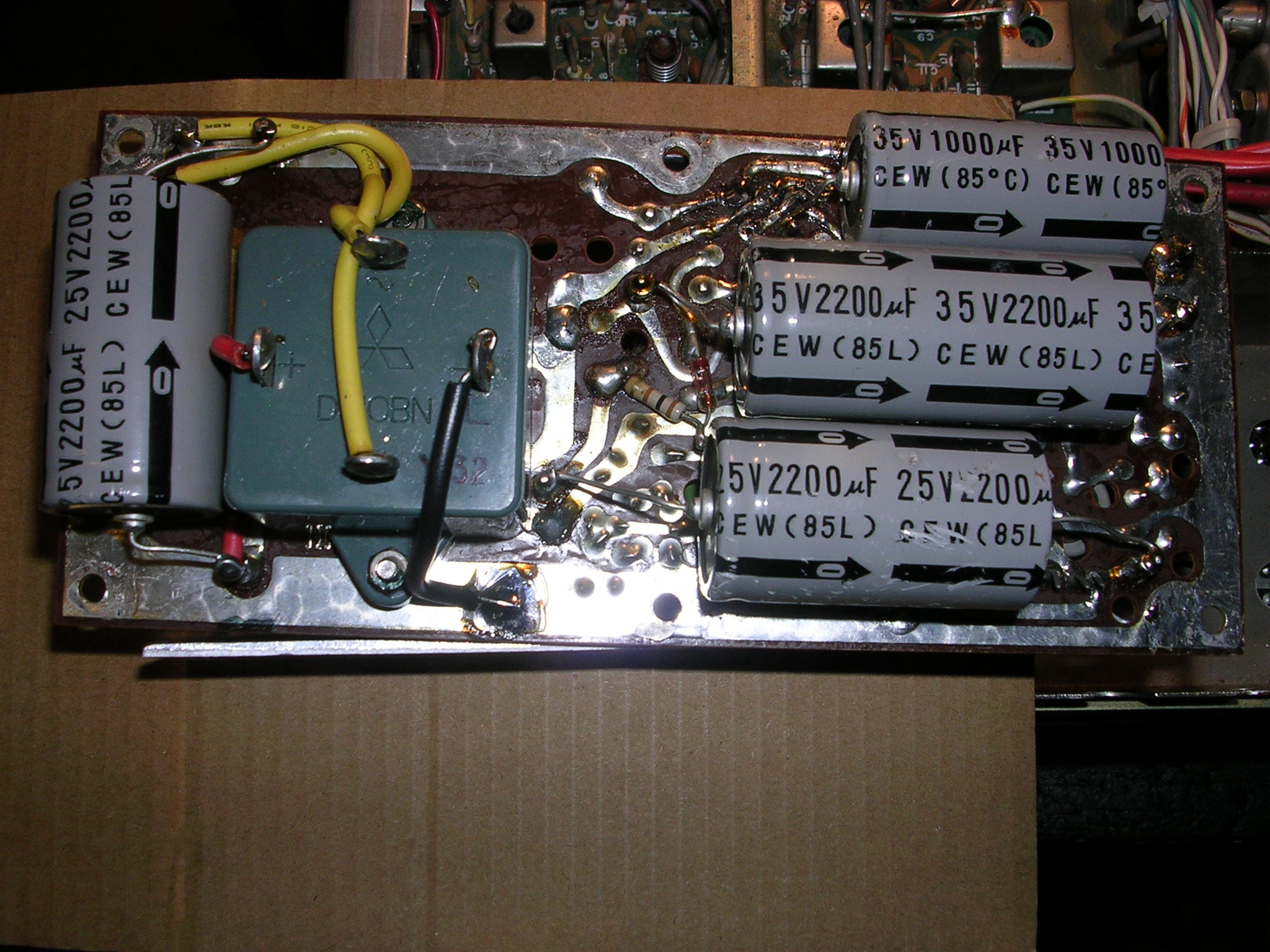
- Keep the large capacitor, C7, at the edge of the board, foil side, dressed well away from the fixing hole. If it is left misplaced, as in the image near the top of this page, it will block the fitting of the board back into the PSU case.The position above is only just adequate!
- Avoid applying test prods or clips to the feed through connectors.
It is all too easy to short the supply rails because not only are they close together, their ground sleeves are very close to the main conductor. (The low power transistors of the Darlington pairs are likely to be destroyed.) - Put some insulating tape over the head of the screws holding the pass transistors onto their heatsink.
- The PSU schematic diagrams and foil side layouts in the service manuals are not to be trusted.
This page was uploaded on
.
© John Everingham